"Czero is one of the best companies I have worked with for analysis and simulation; including dynamic modeling, CFD and FEA. Their deep expertise and comprehensive quality system ensure accurate results. Czero's project management is excellent, providing clean concise information on progress, schedule and budget. Czero is a go-to source for projects ranging from analysis and simulation to prototype product development and testing. They deliver strong solutions to the challenges faced by Offshore and Subsea markets."
World-Class Power Generation Efficiency
Solid Oxide Fuel Cell/ Gas Turbine (SOFC/GT) hybrid systems have the potential for world-class fuel to electrical conversion efficiencies. Czero has partnered with Nexceris and Brayton Energy to develop the next generation SOFC/GT Hybrid Power Generation Pilot System which is funded in part through the United States’ Department of Energy’s ARPA-E INTEGRATE Phase II program.
Nexceris is the prime contractor and leading the development of a novel planar SOFC chemistry and overall stack design, Brayton Energy is leading the turbomachinery and combustor system development, while Czero is leading the overall system architecture design, mechanical design, controls development, construction, and testing at Czero’s facility. This project was awarded in 2020 and will last through the end of 2024.
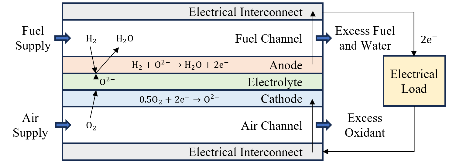
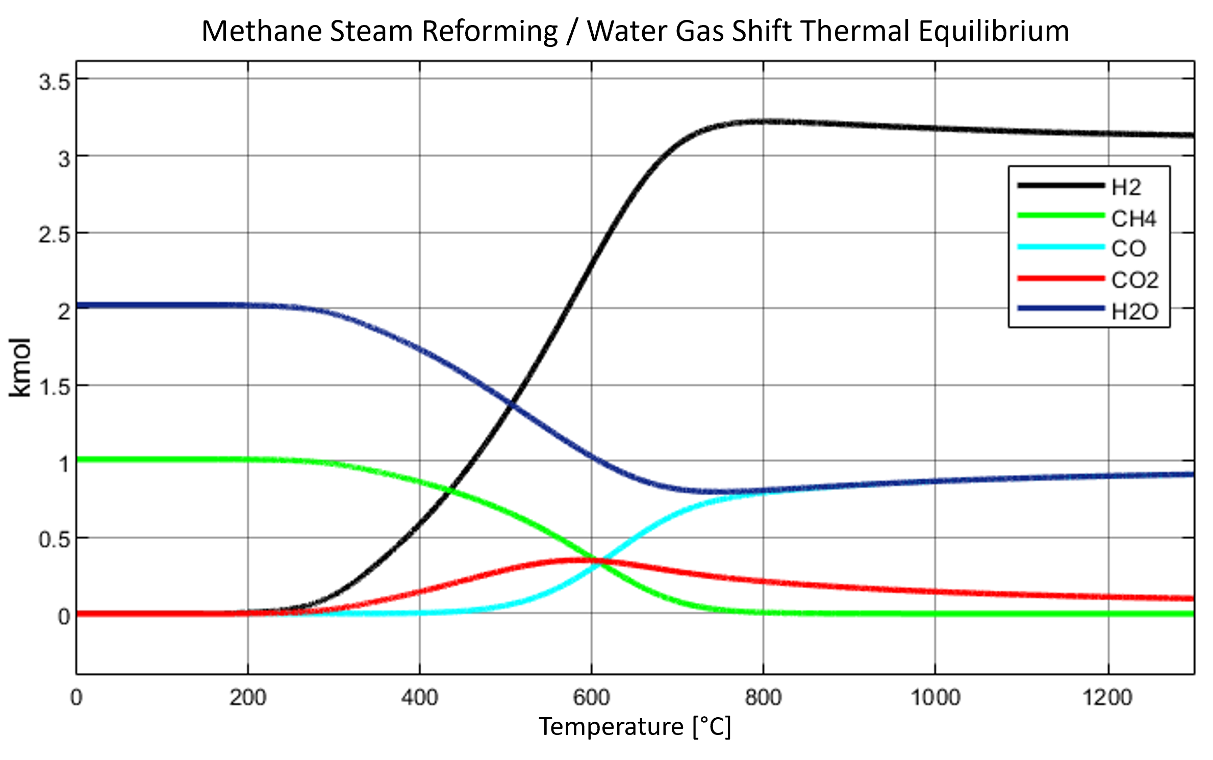
Solid Oxide Fuel Cells (SOFCs) electrochemically convert fuel (including hydrocarbons after Steam Methane Reforming (SMR) and Water Gas Shift (WGS) reactions) directly into electricity at cell efficiencies approaching 60%, while system efficiency generally range 45-55%.
A limiting factor in the efficiency of stand-alone SOFCs is their inability to fully electrochemically convert supplied fuel into electricity as the fuel stream becomes increasingly diluted within the cells. This challenge is generally addressed by only generating electricity from ~70-90% of the supplied fuel while the unreacted fuel leaves the SOFC as anode tailgas. Traditionally this excess fuel is burned to provide heat to support the SOFCs operation. However this approach fails to extract additional useful electricity out of the waste heat streams and overall fuel to electrical conversion efficiency suffers accordingly.
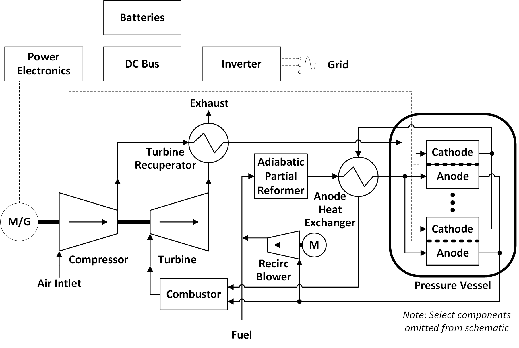
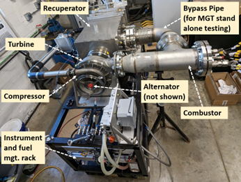
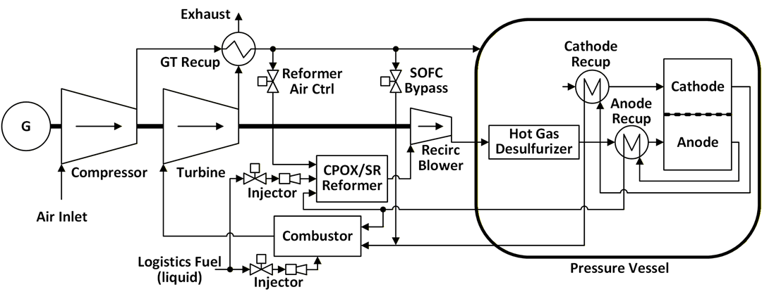
The hybrid SOFC/GT architecture (show below) addresses this deficiency by integrating an SOFC into the hot pressurized path of a Brayton cycle gas turbine. With this configuration the gas turbine’s combustor oxidizes the dilute anode taigas which is expanded through the turbine. The turbine produces enough power to both drive the compressor supplying fresh air (oxidant) to the SOFC and drive a high-speed generator which produces additional electricity (~20% of the system power). While a typical recuperated microturbine has an efficiency on the order of 20-30%, by tightly thermally integrating the SOFC and GT, and operating the SOFC pressurized, the hybrid SOFC/GT system can exceed 70% fuel to electrical conversion efficiency. The overall system efficiency can further be increased by adding a Combined Heat and Power (CHP) cogeneration system.
Quick SOFC/GT Development System Facts:
- Targeted 70%+ fuel to electrical efficiency
- 50 kWe electrical power output
- Natural gas fueled
- Pressurized operation
- High-temperature anode recirculation
- Partial on-anode reforming
- Low NOx/ dilute combustion
- SOFC operating temperature: 850°C
- Turbine operating temperature: 930°C
- Turbine speed: 90,000 rpm
Project team:
- Nexceris: Prime contractor/PI and SOFC development
- Czero: System architecture development, dynamic analysis, mechanical design, subsystem design, controls development, fabrication, and testing
- Brayton: Turbomachinery development


Process Design and System Analysis
SOFC/GT systems are highly complex and interdependent systems. While multiple groups have researched and built various SOFC/GT architectures over the last few decades, there is no consensus on the optimal system configuration. At the project’s onset ARPA-E provided guidance in terms of power level (100 kWe, later changed to 50 kWe), efficiency target (>70%), fuel (natural gas), and that the SOFC should be integrated with a GT in a pressurized configuration. Beyond this guidance the project team was responsible for determining how to achieve these objectives.
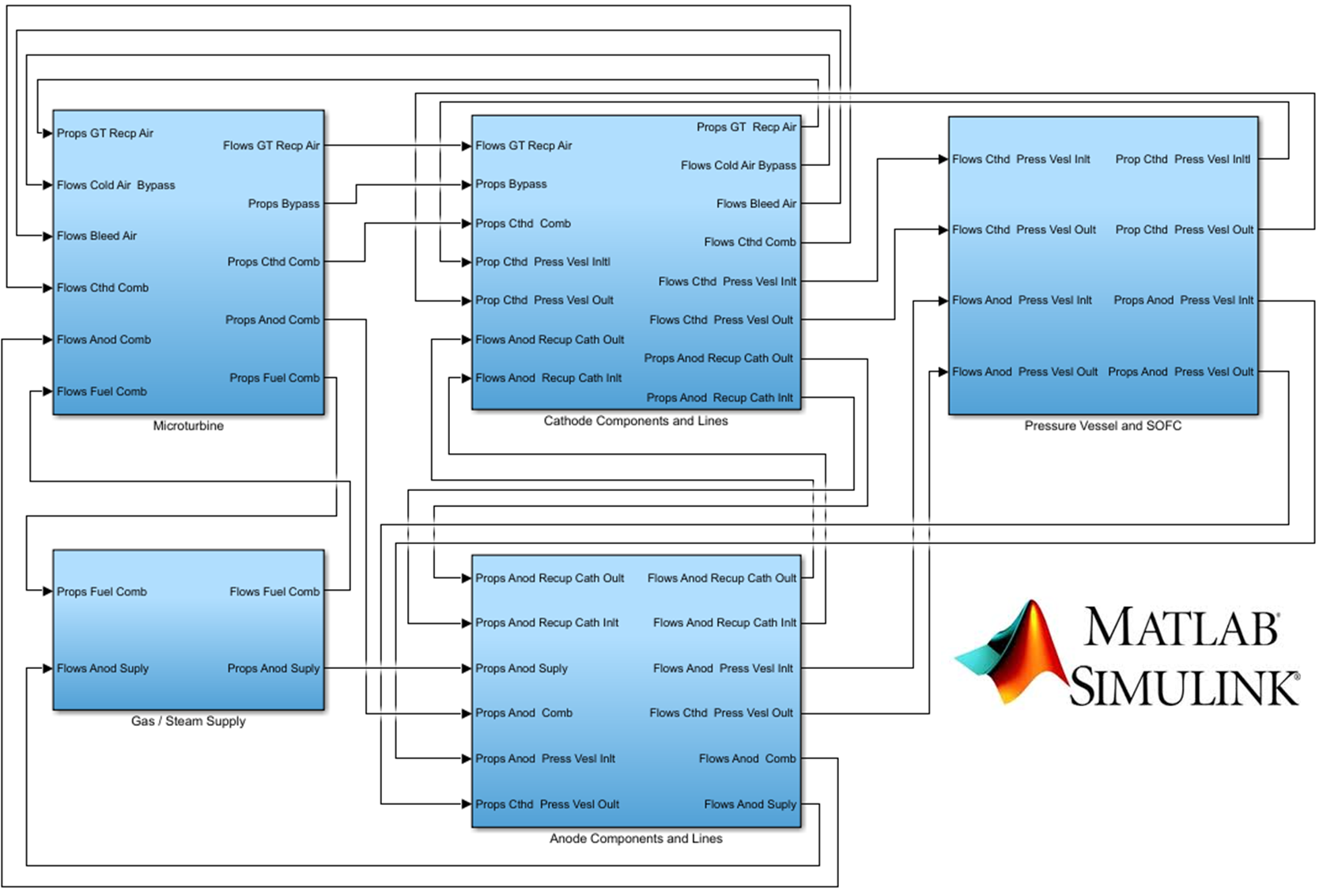
To determine the optimal SOFC/GT system design Czero began with our standard approach of developing a high-fidelity physics-based dynamic model of the system. This dynamic plant model was built in MATLAB Simulink using an internally developed block set and featured tracking of nine individual species, real gas properties (NIST REFPROP), mixture modeling, compressible flow dynamics, equilibrium based chemistry, discretized electrochemical SOFC modeling, and turbomachinery among various other capabilities. This dynamic model was first validated against experimental SOFC and GT data, and then used to explore and optimize the system architecture. Even though the model is highly complex (featuring over 800 states), the model coding is well conditioned enabling average simulation times much faster than real-time. In addition to determining and optimizing the system configuration, the dynamic system model was heavily exercised through a range of startup, shutdown, and failure scenarios (e.g. loss of electrical load on the turbine which could cause rapid over-speeding/ destruction of the turbomachinery). This step is very important for complex systems such as the SOFC/GT architecture as it enabled mitigation strategies to be integrated into the system architecture at an early stage, such as a bleed valve on the compressor outlet to address the lost turbine electrical load failure scenario.
An important aspect of the analysis process is to ensure the dynamic models accurately represent the physical system being simulated. While not always possible due to a lack of data, it is highly desirable to validate, and tune if necessary, at least some version of the system model on real-world data. For the SOFC/GT program the model was validated on both a microturbine and a SOFC, both of which showed good correlation, providing confidence for the system model’s accuracy. Even without this validation and tuning process the physics-based nature of these models provides a strong ability to predict system operation.
In parallel to the dynamic system modeling efforts, Czero developed a detailed Piping and Instrumentation Diagram (P&ID) of the system. The P&ID, along with the system requirement document, serve as key elements detailing the proposed system design ensuring it is well understood and agreed upon between the various internal and external team members.
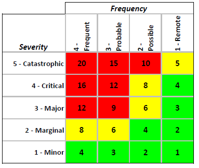
A critical step in the system design process which minimizes risk of harm to personnel and equipment are detailed safety reviews. This is especially important for prototypes as potentially dangerous as the SOFC/GT system which operates at high temperatures (850-930°C), pressurized, with high-speed turbomachinery (90,000 rpm), is filled with hazardous gases (CH4, H2, CO, CO2), and produces high-current DC power (>300 A). One of the more important safety review processes is the Process Hazards Analysis and Hazards and Operability Study (PHA-HazOp). This is a structured approach for evaluating the potential hazards and failure mechanisms of a given system design which Czero frequently leads clients through. In a PHA-HazOp the P&ID is meticulously reviewed, failure mechanisms identified, and mitigating equipment and/or processes determined and incorporated into the system’s design and controls strategy.
Mechanical Design
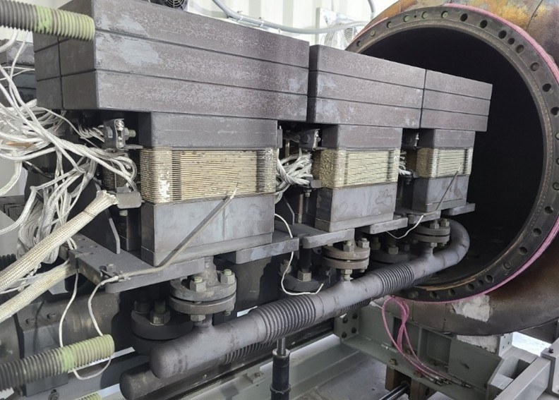
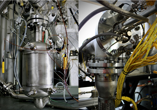
A major portion of the INTEGRATE Phase II project was the component and system level mechanical design, as well as the overall Balance of Plant (BOP) and system integration. One of the core components designed by Czero during this project was the high-temperature (800°C) Alloy 800H pressure vessel which holds the SOFC stacks. This vessel was initially designed by Czero in accordance with ASME BPVC Section VIII, Div 1. A specialized pressure vessel shop was then engaged to review the design, collaborate on design refinements, and then fabricate and certify the vessel. Before being delivered to Czero the vessel underwent post weld heat treatment (PWHT), inspection, and hydro testing.
As part of the design process, Czero produced manufacturing prints of all manufactured components including full GD&T in accordance with the ASME Y14.5 standard. Czero always strives to right-size the mechanical design and design documentation work for a given project to maximize client value. For this project, it was known that this version of the demonstration system would only be produced once. As such, while the full system was largely designed within CAD, many of the minor components were fabricated, and field fit by Czero personnel to avoid the expense incurred through full design prints and external fabrication. However, if the intent had been to produce several of these systems, a full Technical Data Package (TDP) including assembly instruction and operation/ maintenance manuals would have been created, providing the client with all the design information required to reproduce/operate the system on their own.
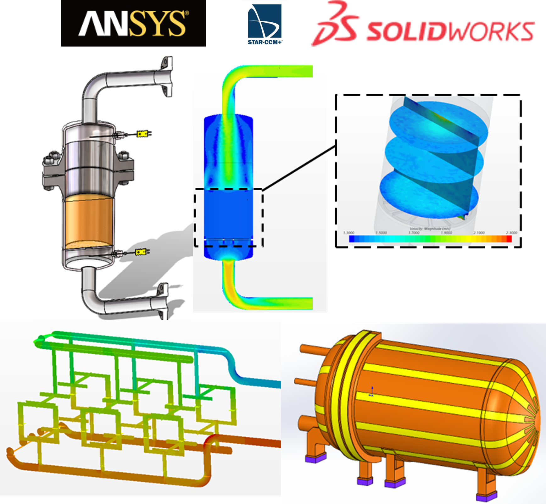
On complex projects such as this, Czero follows an analysis lead design approach to ensure components function safety and as intended the first time. In addition to dynamic system modeling, Czero engineers heavily leverage FEA and CFD to support the mechanical design process. Rapid iteration of the design through FEA on less complex elements is performed by design engineers directly within SolidWorks (Czero’s standard CAD package), while more complex analysis is performed in ANSYS or specialized software like Bentley AutoPIPE. Czero has the full ANSYS suite enabling complex evaluations including coupled transient thermo-structural analysis and CFD (Fluent and CFX). One area ANSYS was used heavily in this project was to evaluate transient thermal stresses within the pressure vessel as the vessel was externally heated by a series of resistive heating elements. CFD was also used extensively in this project to evaluate items such as flow distribution between the stacks, flow characterization of the internally designed packed bed reformer, and convective/radiative heat transfer within the vessel. For this application Czero utilized STAR-CCM+ for the CFD analysis.
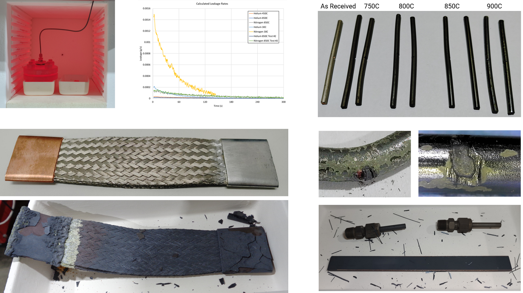
A unique aspect of working in high-temperature applications is the relative uncertainty of how materials will respond under the design conditions. This was echoed by both the high-temperature materials subject matter expert that Czero consulted on this project who advocated that most materials should be tested/verified in-house. As well as by various vendors of high-temperature products who were either uncertain of their product’s performance under these conditions, or whose products failed during Czero’s internal testing even though they were rated for the design conditions.
To address these concerns Czero used an in-house 1200°C test furnace to evaluate materials and processes before implementing them in the system. The most common way a material failed was through corrosion. Even when a component’s steady-state corrosion was at an acceptable level, in multiple cases spallation of the oxide layer during thermal cycling would have been highly detrimental both for the component as well as other components within the system which would have been contaminated by the oxide layer. Czero configured this test furnace to not only allow for automated thermal cycling, but also added passthroughs for pipes and wiring to enable pressurized leak tests on pipe joints, HiPot insulation testing, and measurements of material’s electrical conductivity while components were at full operation temperature.
Another failure mechanism which occurred multiple times, even
with vendors stating a given material was acceptable for these conditions, was
‘glassing over’ of ceramic materials which left them highly brittle and
unsuitable for the intended application. All these material related issues were
addressed in the final machinal design, but they highlight the importance of
thorough testing during development when addressing these issues is much
faster/cheaper/safer than discovering the failures after the system has been
built.


Control System Development
How a system is controlled is a critical aspect of many projects, though too often it is treated as an after-thought. For complex projects such as the INTEGRATE system, it is essential for Czero’s controls group to be closely involved from the project’s onset to ensure a successful project outcome. Not only does this close collaboration ensure the engineers generating the control system develop an intuitive understand of how best to control the system, but there are often multiple changes early in the system’s design made from a controls perspective to improve system robustness and controllability.
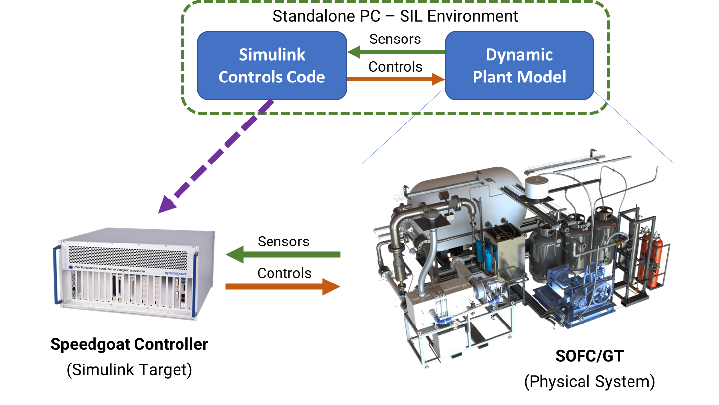
For this project a high-performance Speedgoat platform was selected to serve as the Supervisory Control and Data Acquisition (SCADA) system. Not only is the Speedgoat real-time platform highly capable and modular/expandable, but it also features support for the MATLAB/Simulink environment (comparable to dSPACE, ETAS, MotoHawk, and NI Veristand, all which Czero has used in the past). However in the case of Speedgoat, the MATLAB/Simulink support is native and tightly integrated as Mathwork’s preferred real-time hardware platform. With Speedgoat the entire controls system could be developed in Simulink and then compiled and deployed directly on the real-time target. A key advantage of this workflow for the INTEGRATE program is that full controls code developed in Simulink could be co-simulated with the dynamic plant model (also developed in Simulink) in support of control system development and validation efforts. This process is generally referred to as either Model-in-the-Loop (MIL) or Software-in-the-Loop (SIL), depending on which definitions one follows.
MIL/SIL testing was heavily leveraged during the INTEGRATE program due to the complexities involved with controlling the SOFC/GT system. Control complexities originated not only from the close coupling and interaction of both the SOFC and GT, but also the relatively narrow band of acceptable operating regimes where even small perturbations in temperature, pressure, speed, or flow composition could damage or destroy the very expensive hardware. Furthermore, a hard shutdown (e.g. from an e-stop) could just as easily damage or destroy the system meaning that the control system needed to work well from the onset and controls development work couldn’t realistically be performed directly on the SOFC/GT hardware. As such, MIL/SIL testing was used not only to develop and validate controls during normal system operation, but importantly also for startup and shutdown transients as well as fault injection (such a loss of the electrical load on the GT’s generator which would cause a rapid overspeed/destruction of the turbomachinery unless otherwise mitigated).
One example of a failure mechanism identified during early MIL testing occurred when an inert N2 purge was added to the SOFC fuel stream during shutdown to prevent O2 ingress/degradation of the hot catalyst. While this process may initially seem innocuous, given the large amount of fuel being recirculated in the SOFC, the N2 displaced much of this fuel causing a large increase in fuel entering the GT’s combustor creating a substantial spike in turbine inlet temperature which would have destroyed the turbomachinery. This failure mechanism would likely have been caught during the detailed PHA-HazOp review, however this is not a certainty and examples such as this help illustrate the value of thorough MIL/SIL testing enabling mitigation strategies to be incorporated. Also included in the controls code, and validated using MIL/SIL, was a robust fault detection and response system to ensure the system identified and responded appropriately to various faults which would be very difficult for a human to do (especially given the very large number of warnings and faults evaluated by the system).
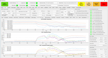
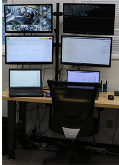
The Speedgoat platform is a real-time system meaning that the controls code is compiled and deployed to the dedicated target and runs at fixed ‘wall time’ rate. Using a stand-alone system is much more robust than running the controls code off a PC (e.g. a NI-cDAQ), especially for safety critical applications. Operators still need to be able to view and interact with the controller while running and this was accomplished using a UI developed in MATLAB App Designer and then compiled and deployed to a test cell PC. The UI allowed the sensor data gathered by the Speedgoat to be visualized and viewed on the PC and allowed the operator to interact with the system such as specifying setpoints and requesting various system operations. Another benefit of a system such as the Speedgoat platform is that it served as both supervisory control and data acquisition systems. All the sensors were fed into the Speedgoat where they could either be used for control, or simply logged for subsequent post-processing. This approach is highly preferred for a development system of this complexity compared to having separate control and data acquisition systems where sensors must either be duplicated or read in by one system and passed to the other. With the Speedgoat system, all sensor and controller data were logged and stored in compressed files and configured to periodically create new log files. This was important for system usability given the multi-day nature of SOFC/GT testing. The logged data was remotely accessed and downloaded to a PC via PUTTY without interrupting the data logging processes, and then post-processed and stitched together in MATLAB for more thorough data visualization.
Given the long duration of system operation (days to weeks) the system was designed with unmanned operation in mind. This was achieved by incorporating sufficient fault detection and fault actions enabling automated response to many issues, the ability to remotely access and monitor the system, as well as an email and text message remote alert capabilities.
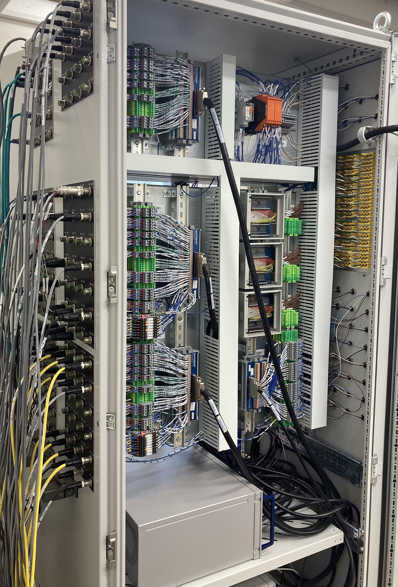
Control system development involves far more than just the controls software, the controls hardware (including sensors, actuators, wiring, and power) and is another important part of the project. Czero designed and built all the controls panels for the INTEGRATE system in-house along with performing the field wiring. This process is aided by detailed panel and wire harness drawings (generated in AutoCAD and RapidHarness), which while built in-house for this project, are designed with enough detail to be reproduced by external shops.
Fabrication, Assembly and Testing
Not only was the INTEGRATE system designed at Czero (excluding the SOFC and GT developed by Nexceris and Brayton respectively), but much of the system was also fabricated, assembled, and tested as Czero facility. A large portion of Czero’s 16,000 ft2 facility is dedicated to fabrication and testing in support of projects of this scale. Given the potentially hazardous nature of this project, a dedicated test cell was created out of two 20’ high-top ISO containers which were located outdoors at Czero’s facility. Given the potential for flammable gases to be present in the event of a system failure, all components within the test cell were approved for C1D2 (hazardous location) operation. The test cell included a high-throughput ventilation system, explosion venting panels, and six gas detectors interlocked into the safety system. Czero also worked closely with hydrogen safety experts to ensure testing was performed in as safe a manner as possible.
Other than the pressure vessel and frame, and high-temperature pipe spools, virtually all the custom components were fabricated in-house at Czero. This improved development speed and reduced costs associated with fully designing/documenting and having external vendors manufacture the parts while also allowing components to be field-fit.
Testing of the SOFC/GT system was split into two phases. First the SOFCs were tested in a stand-alone test system to validate the stacks and allow them to be exercised under a wider variety of conditions than are possible in a combined SOFC/GT system. Second, the gas turbine and remainder of the balance-of-plant was combined with the SOFC and the overall SOFC/GT arrangement was run as a fully integrated system.
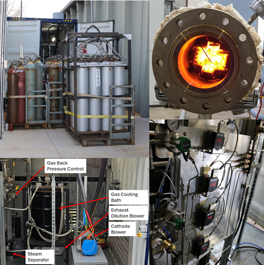
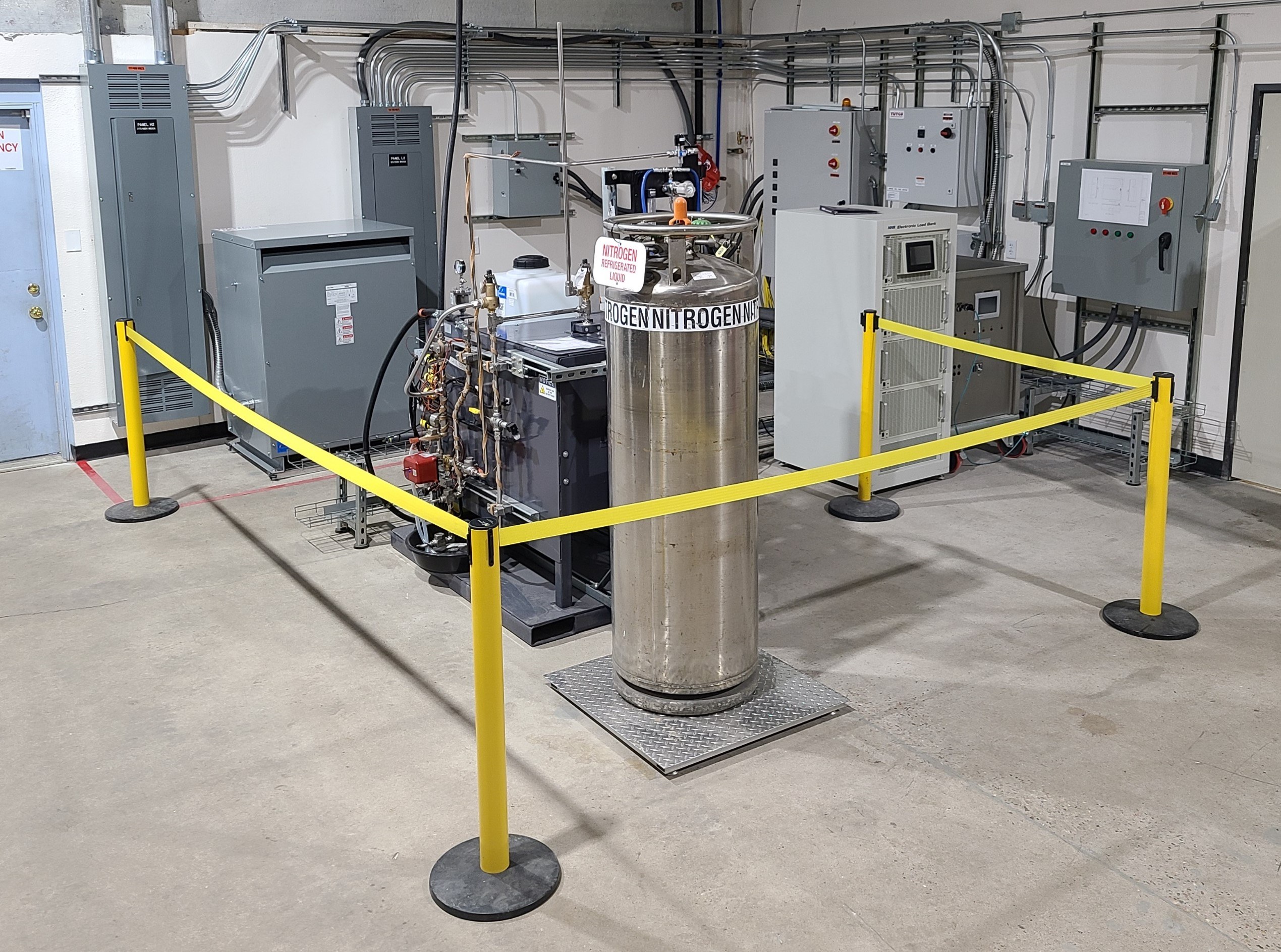
Stand-alone testing was accomplished by incorporating additional components into the system which allowed the SOFC’s inlet and outlet conditions to be directly controlled. These included items such as Coriolis mass flow controllers to mix bottled gas (H2, CO, CO2, CH4) and a steam generator for the anode supply, a variable speed oil free air compressor for the cathode supply, inline heaters to bring the anode and cathode flows up to full (750°C) inlet temperature, and backpressure valves to set the anode and cathode system pressures.
These components, along with a power electronics based load bank to load the SOFC, enable the stand-alone SOFC to be tested in a manner identical to how it would function in the full SOFC/GT system. Further, the SOFC was tested over a wider range of conditions than would be possible in the more constrained SOFC/GT configuration including exploring the impact of pressurization, varying fuel compositions, and varying degrees of internal reforming on system performance. In addition to providing more detailed information on SOFC operation, stand-alone testing also allowed much of the physical hardware and controls system to be tested and validated before the more complex gas turbine was incorporated.
Once the SOFCs were successfully tested, the system was transitioned to the fully integrated SOFC/GT system. This involved removing certain BOP equipment used for stand-alone testing and replacing that hardware with the additional components such as the gas turbine assembly (with a custom rotating group and combustor designed specifically for this program by Brayton Energy based on Czero’s specifications). Removal of the stand-alone test equipment and integration of the gas turbine hardware was done in such a way as to enable relatively easy reconfiguration of the hardware in the future if additional stand-alone tests are desired to further advance the SOFC technology.
Beyond the gas turbine, additional components were also incorporated including an internally developed adiabatic packed bed reformer (to partially convert natural gas into H2 and CO which could be used within the SOFC), cathode recuperator, natural gas compressor and buffer tanks (to address issues with insufficient pipeline pressure at Czero’s facility), and a natural gas desulfurization system among other components and electrical/controls changes.
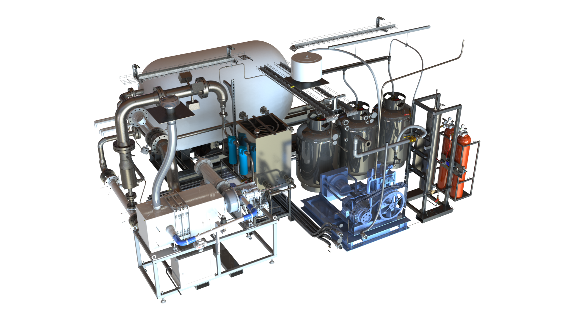
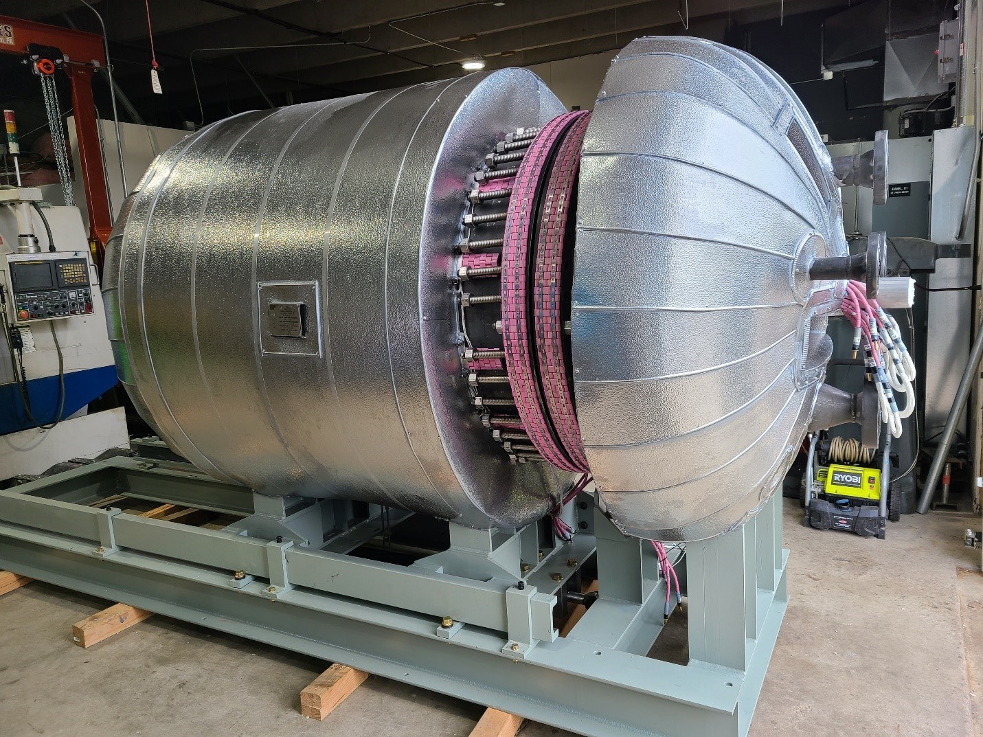
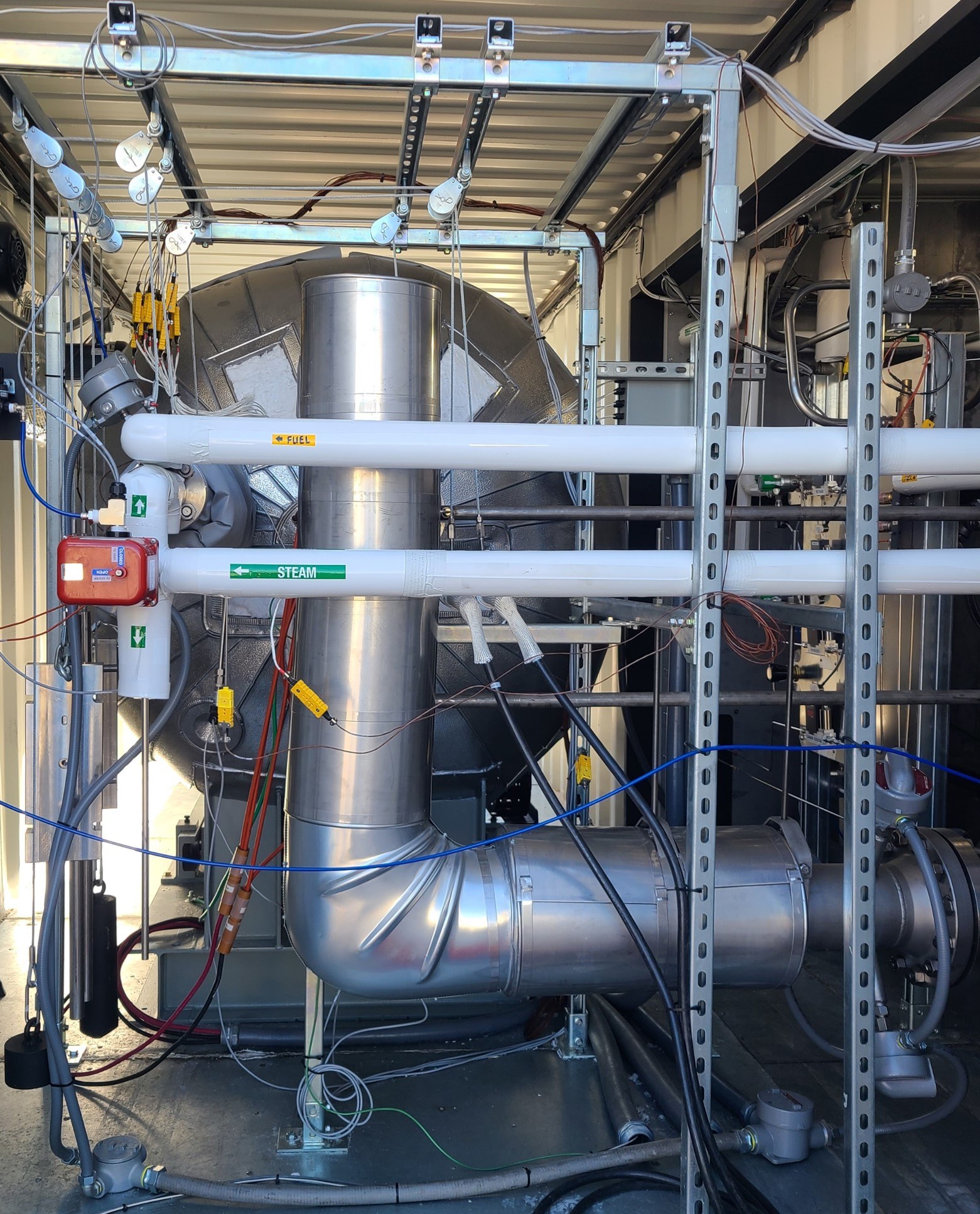
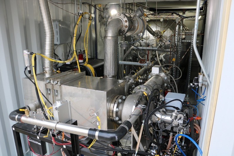
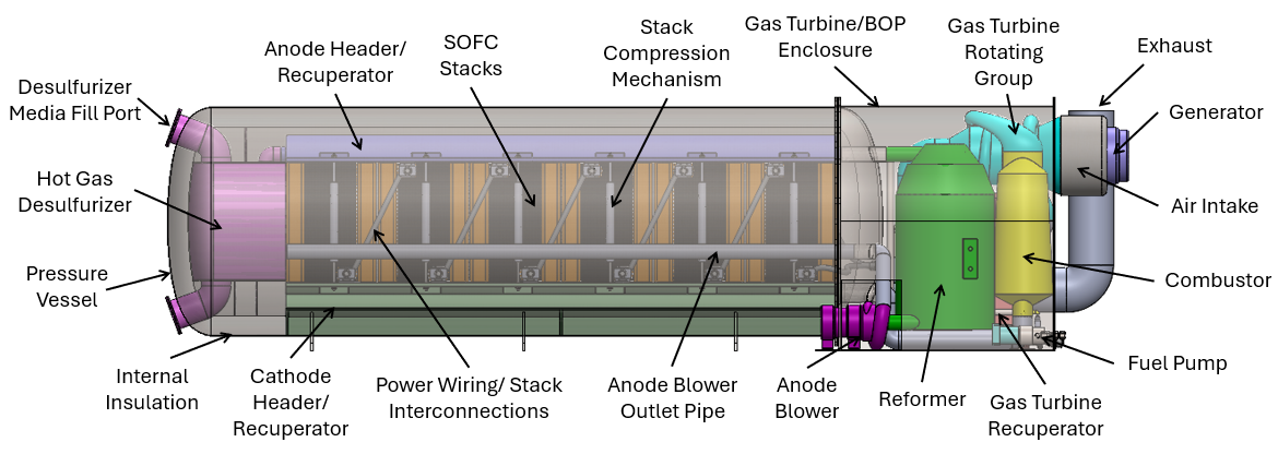
The gas turbine and remaining balance of plant items were fully assembled and commissioned inside the test cell located in Czero’s facility at the end of 2024. An image of the fully integrated SOFC/GT system (before external pipe insulation was installed) is shown below.
In December 2024 the fully integrated SOFC/GT system was brought online and began generating electrical power from both the SOFC and the gas turbine. Unfortunately a few challenges prevented the system from demonstrating the target power generation level and system efficiency. These issues included all the relatively fragile SOFC stacks being damaged during shipment (every shock impact sticker placed on the shipping crates were triggered). During initial curing, the SOFC stacks are fired in a high-temperature retort furnace in part to fuse glass seals placed between the individual cells. When the stacks are subsequently handled roughly (as they were during shipping) these seals can fracture causing the anode fuel to leak out and combust rather than participate in the electrochemical reaction. During testing, as well as from post-test inspection once the system had been shut down, there was ample evidence that seal failures had occurred which reduced system performance.
Another challenge in reaching the target power generation level and efficiency was a lack of funding. There were two significant items which were not integrated into the final SOFC/GT system due funding constraints. First funding limitations prevented the high-temperature anode recirculation blower from being procured and installed. The lack of anode recirculation significantly limited the SOFC/GT system’s ability to reach the 70% efficiency target. Second the system was not fully populated with SOFC stacks, and less SOFC active area relative to the gas turbine power limits overall system efficiency.
Despite challenges faced during testing, the testing program was highly successful in multiple regards. Key among these was that the fully integrated SOFC/GT system was able to be brought up to full operating conditions, reform natural gas into H2/CO, and successfully generate power from both the SOFC and the gas turbine. The system also demonstrated good flow and thermal integration between the SOFC and gas turbine with the gas turbine providing the SOFC with hot pressurized cathode flow while the combustor consumed the fuel in the dilute anode taigas stream to produce additional power in the turbine and generator.
Several areas of initial concern were demonstrated to be addressed by the system architecture and individual components designs. The ability to control system transients and successfully operate both the SOFC and gas turbine in concert had been a key focus. A combination of detailed control strategies refined and validated through MIL/SIL modeling, as well as the selection of design elements such as a two-quadrant motor/generator with an active front end for the gas turbine operated in speed control mode, meant controlling the fully integrated SOFC/GT system for the first time went smoothly and without issue. Another related area of concern was that rapid transients from the gas turbine could create a pressure imbalance between the anode and cathode volumes within the SOFC damaging the stack. However both gauge and differential pressure transducers placed between the anode/cathode streams found the differential pressure remained well within acceptable limits. The necessarily low differential pressure across the SOFC was only obtainable through careful design of elements such as the combustor which was specifically designed to operate with low anode fuel injector backpressure and the development of specific control strategies to minimize differential pressure.
While the project team’s SOFC/GT demonstration system could not meet all the program targets due to issues discussed above, it represents a meaningful step forward in SOFC/GT systems with key learning which can be applied to further advance this highly promising technology.
Future Work
The project team remains committed to this technology and view hybrid SOFC/GT systems as strong candidates for converting hydrocarbon based fuels into electricity at world-class efficiencies. Not only are SOFC/GT systems capable of producing electricity at efficiencies exceeding even today’s most advanced combined cycle power plants, but they do it at a much smaller scale (kilowatt to megawatt scale) than combined cycle power plants (often hundreds of megawatts) while minimizing harmful emissions. This technology may be more important than ever given the rapid increase in natural gas fuel power generation for data centers. Many insights were gained during the first SOFC/GT program and multiple items contributing to the complexity and expense of the first system have already been conceptually redesigned. The project team is actively seeking opportunities for both furthering the current demonstration system, and applying the lessons learned to new SOFC and SOFC/GT systems to advance this impactful technology.
Czero and Nexceris have also been collaborating on SOFC/GT systems for aerospace applications using liquid jet fuel. The aerospace focused power generation system was designed to explore the limits of what may be possible for SOFC/GT system both now and in the future with the latest innovations and advancements.
Acknowledgements
The information, data, or work presented herein was funded in part by the Advanced Research Projects Agency-Energy (ARPA-E), U.S. Department of Energy, under Award Number DE-AR0000956. The views and opinions of authors expressed herein do not necessarily state or reflect those of the United States Government or any agency thereof.
Read about Leveraging Digital Twins Download the Technical Paper
ASME Turbo Expo 2024
Czero's Senior Engineer/Analysis, Michael Sprengel, presented at the ASME Turbomachinery Technical Conference & Exposition 2024.
This paper is copyrighted, here is where you are able to find it to purchase it from ASME directly. Reach out to Czero if you would like to connect with the author.
Sprengel, M., Echter, N. 2024, June. Development and Optimization of a Solid Oxide Fuel Cell Gas Turbine Hybrid System. In Turbo Expo: Power for Land, Sea, and Air. American Society of Mechanical Engineers.
This is the abstract of the project:
Solid Oxide Fuel Cells (SOFC) are an advanced form of fuel cells which can convert hydrocarbon-based fuels into electricity at efficiencies reaching 60%. Fuel efficiency may be increased to 70% or higher by closely integrating a SOFC into the hot gas path of a Brayton cycle gas turbine. SOFCs, unlike more common low temperature fuel cell technologies such as PEM, operate at elevated temperatures between 500°C and 1,000°C, temperatures well suited for integration with turbomachinery. Fuel efficiency is enhanced through several mechanisms including: (1) operating the SOFC at elevated pressure, (2) by tightly integrating the SOFC between the gas turbine’s compressor and expander, (3) by using the gas turbine’s combustor to oxidize dilute fuel in the anode tail gas further heating the already hot and pressurized cathode tail gas before expanding it through a turbine to create additional power, and (4) by eliminating much of the parasitic balance-of-plant (BOP) required to preheat and circulate air through the SOFC. The authors are part of a multi-company collaboration to develop and demonstrate a SOFC/GT system with unique elements such as an integrated cathode recuperator and a fuel to AC electrical conversion efficiency exceeding 70. This paper covers the system’s development with a specific focus on trade-offs and optimizations throughout the system design.
Reach out to us, schedule a meeting, and let's find your custom solution.
We offer concept-to-prototype mechanical engineering R&D for developing systems and subsystems for cleantech innovations. Learn how we can help your team.

- Horst Moll, Former First Chief Engineer, Aker Solutions

"Nexceris has been working with Czero since 2018 to develop and demonstrate a 50-kW scale hybrid power system for a government customer (ARPA-E). Czero led system design and controls development, and currently is leading system construction and testing work on the project. Czero engineers are extremely talented, innovative, detail oriented and responsive. I have thoroughly enjoyed our collaboration and provide my highest recommendation."
- Scott Swartz, Founder and CTO, Nexceris
"PDC Machines- a compression and refueling technology provider to the world’s emerging hydrogen economy has been working with Czero for over 6 years on a combination of greenfield new technology and incremental technology improvements to our product. They have been able to take our napkin sketch frameworks and work with our team to deliver minimum viable product to complete solutions which are efficient, marketable and in many cases patentable. Their clear and simple approach to partnership- working as part of one team PDC staff is why I believe in the growing foundation we started 6 years ago."
- Kareem Afzal, Executive Chairman, PDC Machines
"We chose Czero since they have a stellar reputation for innovation and expertise in the automotive industry. They also have a proven track record and prior history with the original inventor [of Onboard Dynamics natural gas refueling technology]—who is on our team—that has already resulted in huge successes in meeting critical milestones and performing to expectations."
- Rita Hansen, CEO Onboard Dynamics
"I have a >$1M US Department of Energy research effort for which I was understaffed and lacking specific subject area expertise. Czero was able to engage last minute to displace a well-known automotive engineering company at a fraction of the price. Over a year into the project, Czero has continued to be responsive and trustworthy; their engineering performance has contributed significantly to an increase in project funding from the sponsor. As the project principal investigator, selecting Czero as an engineering services company has been one of the best decisions I have made."
- Chris Hagen, Assistant Professor, Energy Systems Engineering Oregon State University – Cascades
"Czero’s work with us to fully understand the requirements of the end product for the new reactor engine system has been instrumental in developing a completely new, innovative system. From these requirements, they were able to quickly come up with multiple concepts for vetting against the tough project objectives, which include not only technical feasibility but also aggressive cost targets. The in-depth simulation and analysis of the various concepts that Czero did ahead of time has built tremendous confidence we are going down the right path."
- Devin Halliday, Principal Investigator, Gas Technology Institute
"Czero’s ability to work with our engineers in developing innovative, ground-breaking technology has been a great benefit to the SuperTurbo development. We have placed a lot of trust in Czero’s ability to deliver and have not been disappointed. They are a top-shelf organization."
- Tom Waldron, Executive VP, SuperTurbo Technologies

“My initial request to Czero was to develop software and the associated controller needed for a very important competitive assessment of our product. Due to the nature of the project, I needed the work to be accomplished and in my customers hands within 2 months, which was a very aggressive necessary timeline for this level of work. Not only did Czero get the software and ECU requirements done to spec, but the system was delivered to my customer ahead of time to support the testing. The expertise, timeliness, and quality of the Czero solution was outstanding!”
- Bradlee J. Stroia Ph.D., Stanadyne Operating Company LLC

"We’ve had an absolutely fantastic, positive experience with Czero and I wholeheartedly endorse them. They are more than a typical ‘throw it over the fence’ engineering consulting firm, as Czero not only develops a strong understanding on the background of the project, but they also think along the way and offer suggestions and ideas beyond the scope of the simple engineering contract deliverables. And, they deliver, too. They are really solid, outstanding people."
- Steve Kloos, Former CEO AquaHydrex

"The engineers on the Czero team were proactive problem-solvers from our first introduction. They quickly applied the full breadth and depth of their engineering team’s impressive intellect to determine the most efficient and cost effective system to maximize the energy-harvesting capabilities of Brown’s concept.
They were remarkably objective in their trade studies to find the best solution, favoring a simpler mechanical solution over their greatest strength: advanced hydraulics. They walked us through potential failure modes of each system, and educated the team about the pitfalls of component scalability. In addition to their technical solutions, Czero did an excellent job conveying their thought process and analysis to the Brown team with clear graphs, diagrams and presentations, which streamlined decision-making.
Czero added tremendous value to the Brown project and was a pleasure to work with. We look forward to putting our heads together on future projects."
- Tom Derecktor, CEO
"Czero has been an invaluable and integral part of our program. From component and subsystem design to detailed system performance analysis, Czero’s integrated engineering approach has allowed us to develop elements quickly to meet the very ambitious schedule challenges imposed by our U.S Department of Defense contract."
- Scott Frazier, Co-founder and CEO

"Czero has been a valuable strategic partner in helping FACTOR[e] startups advance technologies quickly while staying lean during their crucial first two years. We know Czero’s agility, creativity and process. We trust their team. We’ve seen their technology insights and the business value of what they deliver."
- Morgan DeFoort, CEO
"As we move from R&D to commercialization, Czero is providing top-notch engineering support to our team, transforming our ideas and concepts from prototype designs to viable commercial products. Czero really digs into the requirements before starting the design process, enabling us to easily collaborate on design options that optimize our product designs to meet market demand and ensure customer satisfaction. Without hesitation, we recommend Czero to anyone wanting to accelerate R&D and product development."
- Steve Witt, CEO, OptiEnz Sensors
"Czero understood our test objectives very quickly and communicated systematically to define the test procedure, scale model details, and test fixture that fulfilled all test requirements quickly and safely. They creatively utilized off-the-shelf items in the scale model to keep its cost low and provided a clear, concise report—including useful insight—within a week of test completion. Helix is very pleased with the service provided by Czero."
- Roy Cottrell, Engineering Manager, Helix ESG

"With extensive experience in engine systems design, Czero played a vital
role in helping Logimesh expedite concept-to-prototype development and
testing of our award-winning Logimote engine health monitoring platform."
- Bill Gillette, President & CEO, Logimesh Technologies, LLC
"Czero was the right partner to help us design our custom grist bin and bag intake station. They found the perfect balance between a properly engineered solution, a cost effective solution, and an aesthetic solution."
- Bryan Hermann, Technical Director, K-MALT

"The true sign of individual or organizational dynamism is the willingness to take risks. It signals real confidence in capabilities and know-how, the flexibility and creativity to explore and test new solutions, and guts to do what it takes to deliver under real economic and technical uncertainty. Czero epitomizes those characteristics and combines them with old-fashioned integrity and reliability. Needless to say, their engineering and technical capabilities are superb. As a young company commercializing real black-box technology, we've entrusted Czero with taking responsibility for critical design and engineering tasks for which there are no precedents, i.e. it has never been done before. They have delivered, under demanding time and resource constraints, and set a very high bar. Culturally and otherwise, they are an ideal partner for young startups who need deep-dive, blank-slate engineering solutions. I would recommend them to anyone."
- Richard Kinsman, former President & CEO, CO2 Nexus Inc. (now Tersus Solutions)
"Czero was an insightful and very technically proficient group that were instrumental in helping us develop our technology. They were very quick studies to understand the fundamental challenges we faced and design/build solutions around them. Top qualities: Great Results, Personable, Good Value.
- Doug Henston, Former CEO, Solix Biofuels
"Czero understands technology development from the back-of-the-napkin stage to the product launch stage. I've never met a team who is more capable of keeping the end-product vision in mind during the early stages of engineering."
- Sam Jaffe, CEO, Panea Energy
"Czero provided a custom engineering solution to our need to convey conceptual functionality. Their approach was creative, effective, high quality and fast. Highly endorsed."
- Rick Dunagan, Partner, Symbiotic Solutions
"To work with Czero is nothing short of a privilege. Stemming from their excellent credentials and strong analytical aptitude, they consistently translate complex technical situations into plain English to allow multidisciplinary group to function together seamlessly."
- Nick Rancis, Co-Founder and Principal, Tierra Verde Consulting LLC
"I was extremely impressed with how quickly Czero understood the needs and intent of the bearing housing design and how responsive they were in completing the drawing package."
- Scott Taylor, VP of Engineering, TMA Global Wind Energy Systems