DoE funded mobile gas reactor
The goal of this project was to develop a low cost, mobile gas reactor that could be used to convert undesirable well gases that are typically flared into valuable commodities. Historically these byproduct gases are flared as the transport of them to an off-site processing facility is not financially feasible and therefore, they need to be flared for safety reasons. By creating a mobile reactor that can be taken directly to the wells, the gases can be converted into higher value products that are more readily stored and transported. This project was funded by the U.S. Department of Energy (ARPA-E). The Gas Technology Institute was the prime contractor and the team included Czero, Oregon State and EcoCatalytic.
Dynamic modeling of a novel gas reactor
While the intent of this novel reactor design was such that it could convert a wide range of gases, the first prototype was designed specifically to convert ethane to ethylene. The mobile reactor was based upon using a repurposed reciprocating engine that is readily available and low cost. A dehydrogenation catalyst is used to improve the conversion and is regenerated every cycle to ensure good conversion.


Project overview
- Internal combustion engines (ICE) are relatively inexpensive, abundant and durable. This project examined repurposing an ICE to create a high throughput, scalable gaseous chemical reactor. Czero was responsible for the analysis, design and build of the reactor. This webpage focuses on the modeling of the process.
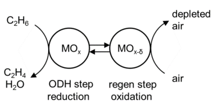
- The project demonstrated the following chemical process: Converting ethane (C2H6) to ethylene (C2H4) using oxidative dehydrogenation (ODH) reaction mechanism in a catalyst, as shown in the ODH process for converting ethane to ethylyne image, to improve yield and reduce energy use and emissions.
- The technology potential of this engine reactor is a machine that is efficient, economical, portable, scalable, and with low emissions.
Process description
- Feed stock (ethane) is compressed in-cylinder to 850 °C and 25 bar and passed through catalyst loaded with oxygen. Catalyst reactions strongly favor ethylene production at these conditions.
- Ethylene removed from reaction zone (catalyst) at product exit port and catalyst zone flooded with air at 377 °C and 25 bar to reload catalyst with oxygen for next cycle.
- Excess air removed at exhaust gas port and catalyst zone re-flooded with feed stock stream from compression cylinder for next cycle.
Modeling methodology
This project used the GT-Suite software platform to model the process. Of particular interest was maximizing the volumetric efficiency of the ethane and air compression processes as well as minimizing the heat losses in the reactor minimizing the power consumption. The modeling objectives were two-fold:
- Maximize the mass of product output per mass of reactant input by maximizing volumetric efficiency and minimizing product/reactant mixing in the reaction volume.
- Minimize energy consumption per mass of product output by reducing cylinder and head heat transfer, and maximizing conversion of ethane in the reaction volume.
Reactor design criteria
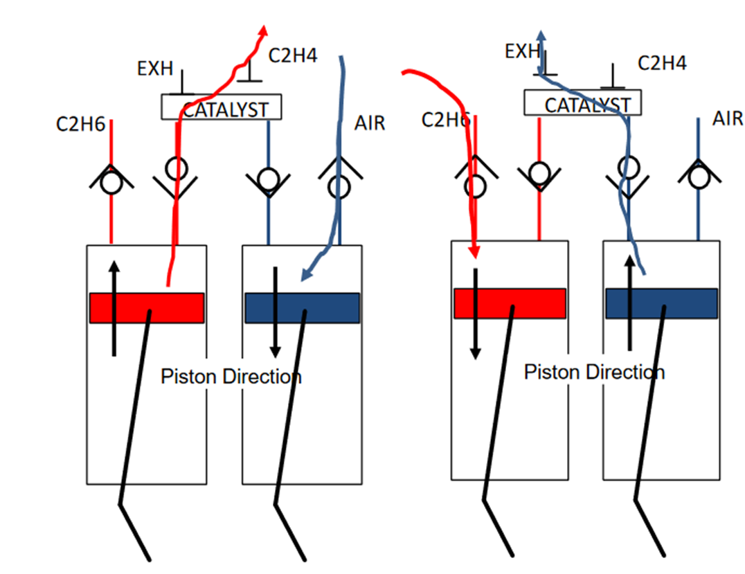
Two basic conceptual designs were analyzed using GT-Suite. One involved 2-stroke operation of two separate cylinders phased 180 degrees apart. The other involved 4-stroke operation of a single cylinder with intake porting from both the ethane and air supply. The two-stroke concept is shown in the Two-stroke reactor concept image. The left side cylinder is dedicated to ethane compression and the right-side cylinder is dedicated to air compression for catalyst regeneration. Active fixed valve timing is used to time the flows correctly and optimize the throughput while minimizing the product/reactor mixing in the catalyst. The following design space was explored with the model:
Numerous design options were explored including:
- 2-stroke/dual-cylinder and 4-stroke/single-cylinder operations
- Catalyst location in the engine head or in-cylinder
- Catalyst flow directions forward or forward/reverse
- Poppet, rotary, and check valves
- Passive or active valve operations, fixed or variable timing
- Pressure regulation before or after the catalyst
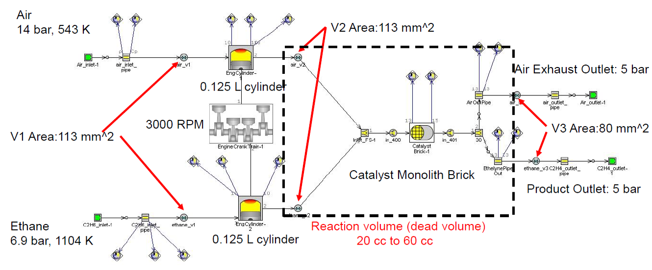
Simulation results were analyzed, and the following options were selected using the GT-Suite model shown in Two-stroke reactor GT-Suite model image.
- Catalyst in head with forward flow direction for both reactants
- Check valves used for cylinder inlet/outlets.
- Active rotary valves used for outlet valves after catalyst that direct flow to product or air outlet.
- Variable valve timing on outlet valves (phased only, no duration changes)
- System pressure regulation performed after catalyst.
For more information, see our Whitepaper/conference paper
Reach out to us, schedule a meeting, and let's find your custom solution.
We offer concept-to-prototype mechanical engineering R&D for developing systems and subsystems for cleantech innovations. Learn how we can help your team.